How did we manage to transmit ever more digital signals with fiber optics? How do we shape light?
This blog post is not an introduction to fibers or optical components. If you want one, read this. Then read books, or ask me to write more articles!
The simplest digital modulation formats
A digital signal is a stream of 0 and 1. In order to transmit it, the simplest idea is to send each period 1 bit using either an high or a low intensity signal. This is called On-off keying (OOK). In the following animation, you can see the intensity in the fiber over time:
click to change the next symbol sent
drag left-right to change the clock frequency
Couldn’t we be subtle? If we can tell them apart, why not use multiple intensity levels - and send 2 bits per period?
The different chunks of signal we send are called symbols. Here, we encounter a powerful idea of signal transmission:
At a given frequency (the baud rate), we can send more or less information depending on the number of symbols we use.
Compared to more advanced modulations, turning the laser on/off or sending pulses can be done easy be directly controling the power sent to the laser/LED1. This is called direct modulation.
From bits to symbols
We may want to avoid long sequences of 0 or 1: they may put the receiver clock out of sync! Because of this, we will avoid a direct encoding from bits to symbols. We can use a line code to embedd a clock in the signal, use a scrambler to remove unwanted harmonics, or even solve ambiguities in sophisticated modulations.
We will now ignore bits and line codes, and focus on symbols!
Reminder: optical fibers use light!
Optical transmissions use… light! Talking only about the signal intensity is too simplistic. We are dealing with electromagnetic waves, and we will be using a laser signal – tuned at a specific wavelength – to carry information.
Here could be a representation of the unmodulated signal lasers sends:
Our amplitude-modulated signal might look like this2:
Reminders: the intensity we drew earlier is a mean of the square of the raw signal.
Dividing the spectrum into wavelength channels
We can send multiple signals on a single fiber, each carried by a different wavelenth/frequency. Each receiver will filter the frequency it wants to read. This is called Wavelength division multiplexing (WDM).
Does it mean we can send as many signals as we want? Not quite.
Signals don’t occupy a single frequency
How come our amplitude-modulated signals spread over an interval of wavelengths?
- Lasers are not precisely tuned, and this forces you to use some margin. For the best precision you must stabilize their temperature.
- Modulation widens the carrier signal’s spectrum. The extra frequencies are called sidebands. They span a bandwidth whose order of magnitude3 is the data frequency (~10GHz).
Because of this, we are forced to use channels, separated by guard bands to avoid interference4. The next 3 figures are from an amazing presentation on optics
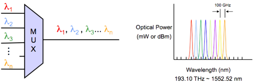
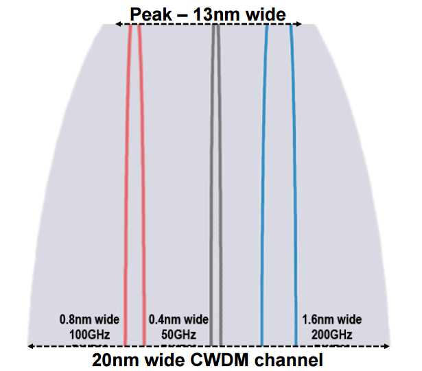
Over the years, better WDM technology (Coarse/Dense/UltraDense) led to ever narrower channels:
Optical fibers' usable frequencies are bounded
Optical fiber are not perfectly transparent. There is always a loss: eventually we can’t tell the signal apart from the noise. This signal attenuation depends on the light’s wavelenth:
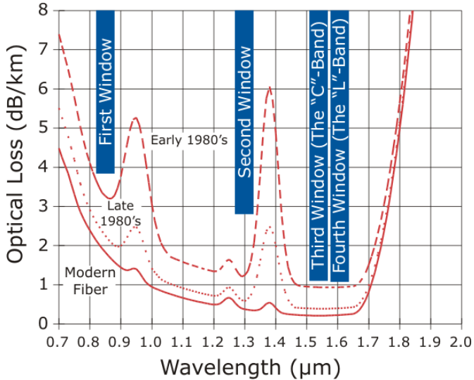
There are more restrictions5! Optical amplifiers can only be used with a limited range of wavelengths… All others are limited to short-range applications.
Today, we can use up to 88+ channels in each fiber. Ultra-Dense WDM will push the enveloppe further.
When does direct reception stop shining?
Soon online: “What limits optical transmissions?”
So far, all seems great: to send more data, we can increase the baud rate, use more complicated symbols, or occupy more WDM channels. However, we quickly encounter different problems:
- Noise is killing us on long distances. Can we send symbols more distinct than intensity levels?
- The sidebands of amplitude modulation are a big problem: they introduce chromatic dispersion, very sensible beyond 10Gbaud.
- The clock rate of our electronics (digital-electronic conversions) is ultimately limited. 60Gbaud is the ceiling.
If you need to build a data transport network across the globe, you need a better6 technology: coherent optics.
The next step: Coherent optics
Optical signal constellations
How do we send even more information? We can start by modulating both the carrier’s amplitude… and phase.
Soon online: “What do we mean exactly by coherent optics ? How do we modulate and recieve the phase?
In Binary Phase-Key Shifting BPSK, we send symbols by shifting the signal by half a period.
The signal is now the projection of a late/early clock.
If you add two of those signals, you can have 90 degrees (quadrature) shifts: QPSK7. Notice how the symbols are much farther apart than with intensity modulation:
On the left, you can recognize the symbols used.
Constellations can be even fancier by modulating both phase and amplitude. Here is what 8QAM looks like:
Signal over noise requirements end up limiting the constellation complexity.
Soon online: “How do receivers and transponders coherent optics work?”
Polarization multiplexing
Earlier we mentionned that light is a wave, and that led us to exploit wavelength multiplexing (WDM). This said: in which direction does light oscillate?
In optical fibers, light is a transverse wave: it can oscillates in directions perpendicular to the fibers' longitudinal section. Luckily for us, receivers can be made to tell apart two orthogonal polarizations.
We can send different data on each polarization:
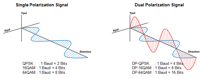
Dual-Polarization (DP) gives us twice as many bits as before!
Smarter constellations?
The gap in bits-per-symbols between constellations is large:
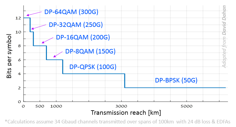
If (maybe because of the noise level) we cannot use DP-8QAM, we have to settle for DP-QPSK, thus losing 33% in bit rate. Can we be more flexible? Can we find something intermediate between DP-8QAM and DP-QPSK?
It turns out we can try to use a combination of a higher-order modulation than we can afford, but with a smart line code:
- In polarization multiplexing, we always send a even number of bits per symbol. However, we can sacrifice a bit of data for a “checksum” bit. Implementing this in a smart manner is not easy; it means finding constellations in the 4-dimensionnal space of dual polarization symbols… Read about Set Partitionning 4D.
- Probabilistic Constellation Shaping offers to use less the high-energy symbols, as they suffer more from noise.
- Line codes can use correlated successive symbols.
What might be next?
Are you interested? Our group works on optimizing optical networks using those technologies… We’re hiring!
Send the control signal to a basic transistor. On the receiver side, a photodiodes will directly convert your light intensity directly into electrical current. ↩︎
In reality the frequency of the modulation may be 20k slower that the signal’s. ↩︎
How much spectrum is used depends on the modulation. Spectral shaping can limit the bandwidth used and improve intersymbol interference. ↩︎
The grid can be broken down for even better spectral efficiency and flexibility. Read about WDM flex-grid and super-channels. ↩︎
Chromatic dispersion is also limiting. It also depends on the wavelength, and is also limiting outside of the “good” wavelengths. This said, it is not the main limiting factor as we can compensate it with Dispersion Compensated Fibers (DCF), or DSPs. ↩︎
Coherent optics are more expensive, may use more power, occupy more physical space, and generate huge amounts of heat! But there is no choice anyway. ↩︎
Smart line codes and variants can avoid symbol transitions through the origin. ↩︎